Pattern Matrix V2 report
Posted Aug. 28, 2017 by FoAMWe've been busy making a new tangible interface – the Pattern Matrix is part of the ERC Penelope project, which explores mathematical proofs embedded in (weaving) pattern, and how technology defines our relationship with the world. The new interface allows the user to play with weaving pattern quickly, and crucially allows mistakes – meaning we can start to understand the mathematics embedded in the patterns. As Margaret Wertheim says in her book about crocheting the foundations of geometry - 'Here, knowing emerges from hands performing mathematics: it is a kind of embodied figuring'
The pattern matrix version 2 is now complete. This post outlines what we’ve done, why and how.


Electronics design
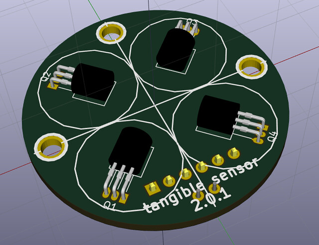
Each pattern matrix tangible sensor is made from 4 Hall effect magnetic sensors and a capacitor to smooth out any noise on the power coming in. The difficulty with this Printed Circuit Board (PCB) is arranging the sensors so they align with the magnets in the tangible token in the optimum manner. From tests with our prototype Lego rig, this isn’t actually too critical – but it’s set up so the lead length can be tweaked at soldering time to move them closer or further apart.
This took about 20 variations to finally get right using KiCAD, but the circuit is just about simple enough that it can be made single sided – this is good because the top side will be partly exposed, while the lower side with all the copper traces can be protected. It’s good practice to have large areas of copper left connected to ground, partly as it’s a common connection needed all over the board, partly for stability but also it reduces the amount of chemicals required to etch the circuit – as only the parts around the traces need to be removed.
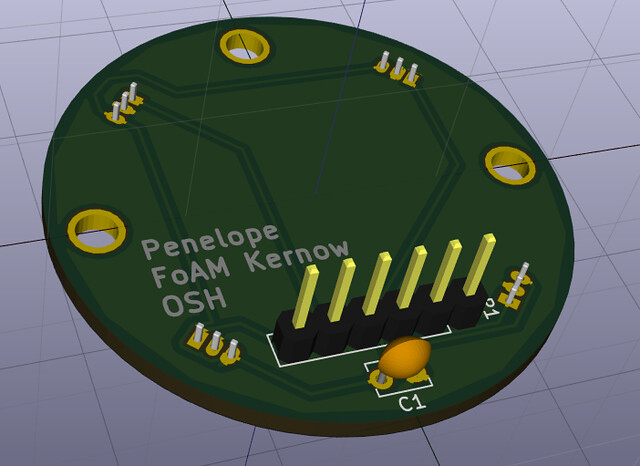
The expander PCB which connects to these sensors is made to be modular, so we can stack up any number and connect them to the Raspberry Pi for different arrangements of sensors. Each board can deal with 8 sensor locations (each comprising 4 individual Hall effect sensors). Their job is to convert the digital signals from each sensor into serial data so the Raspberry Pi can read them all just using 2 wires.
Hardware fabrication
Our focus on Appropriate Technology means we want to find ways of making things that are low resource and re-usable – we also like to make it so nothing is hidden, so it becomes clear that building your own technology is achievable. The antithesis of modern technology, which is often hard or impossible to fix or recycle, and with all-too-common regularity requires proprietary tools to even open to case. We wanted to move away from the problematic materials used in the Pattern Matrix V1 (predominantly plastic and aluminium), and so decided to make V2 from wood.
Recently we’d met Aaron Moore – he’s an interesting person with quite a backstory, having ditched university and upped sticks to Kenya, teaching people how to make handtools for a decade (a previous scheme had taught carpentry in the area, then finished, leaving the locals with no tools with which to continue their trades). Aaron’s now set up a rural makerspace near St Agnes in Cornwall – he has hand tools and machines for traditional wood working, a forge for metal work, and has built his own enormous CNC machine (for reductive milling), large-scale 3D printer, and laser cutter, all using open source technology. Someone with such fine skills in traditional crafts, combined with the foresight and ability to build digital manufacturing machinery is a rare find – with some funding from Cultivator, we arranged to go to Aaron’s makerspace and learn from him.
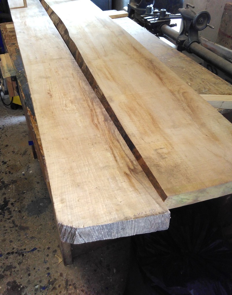
We started right at the beginning, taking apart hand tools to see how they are built, sharpening blades the right way, and making a mortise joint fully by hand – fully appreciating the behaviour of the material and the labour required. We then stepped forward a few centuries, using mechanised equipment – drill presses, band and table saws, planing and sanding machines – to make the pieces for the Pattern Matrix. We chose to use beech to match the wood in the traditional looms that will be in the same exhibition. The wood we bought turned out to have a fungal infection resulting in beautiful patterns known as spalting. This is uncommon if you buy wood from mass-produced commercially grown trees. It’s tricky to work with because the material is less uniform in strength – the paler areas are more brittle and flakey. [Having spent the last year doing a formal horticulture qualification on the side, learning to work with wood closes the loop, allowing an exploration of the properties of the plant material itself – a small win for circular learning.]
The design of the Pattern Matrix V2 frame is five simple pieces that fit into two end pieces using pegged mortise joints. This allows it to be taken apart for easier transport, and for recycling at the end of its life.

Building the sensors

After triple checking the schematics and design files and ordering 80 PCBs there was an anxious wait for them to arrive and do some initial tests to find out if there were any mistakes.
The circuits worked fine, the only problem that came up immediately was that the soldering pads on the Hall effect sensors are very close together - but with a new soldering iron and a bit of practice it was possible to build the 25 quite quickly.
The blue 'jumpers' on the square boards allow you to set the ID of the board so the Raspberry Pi can tell them apart – these could alternatively be hard soldered, but it’s good to have the option to reuse the parts or reconfigure a pattern matrix so we can add different sensors etc.
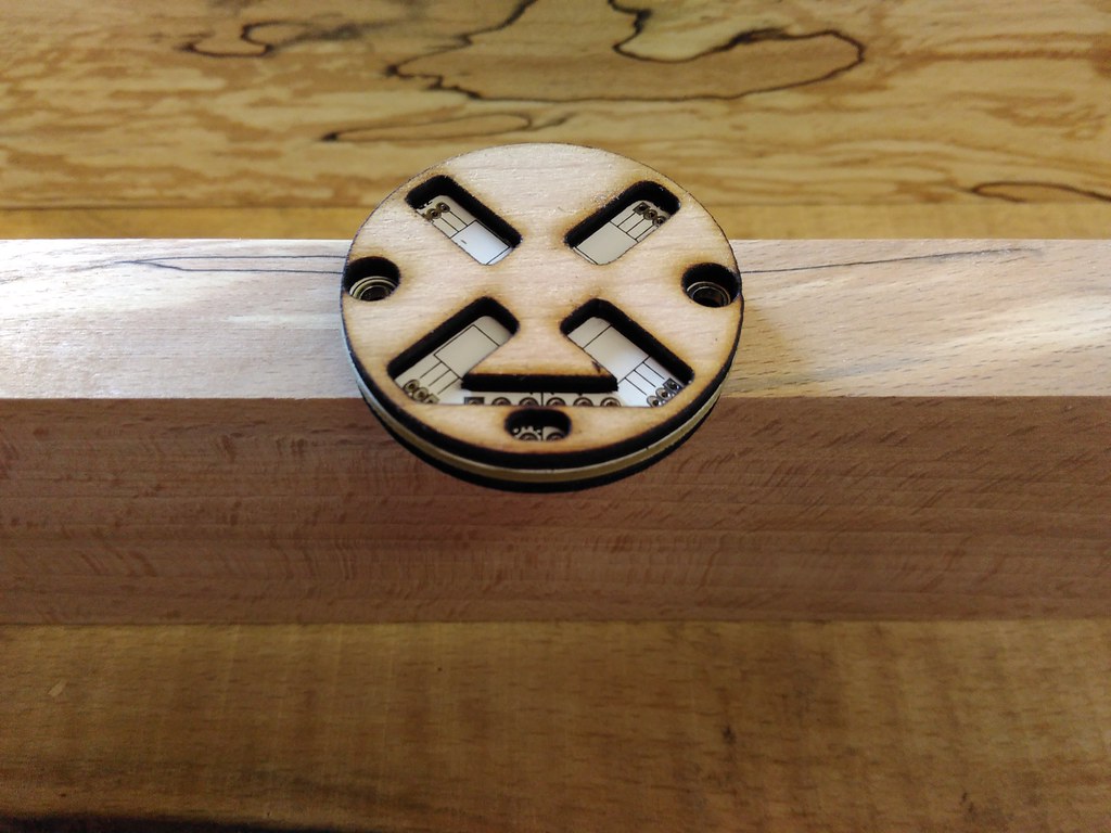
Laser-cut pieces were designed to protect the sensor PCBs – with one piece underneath cut from 1.5mm birch ply, and another piece on top cut from 1.5mm birch ply with 1mm beech veneer (veneered by hand). The top piece needed to be thick enough to protect the Hall effect sensors from being bashed by the token controllers, and the beech veneer meant they would match the main frame more closely. The covers were attached to the PCBs using clear silicon sealant which is strong, but allows then to be separated using a scalpel blade if necessary. The sensor pieces were then screwed onto the main frame using small screws (MF-ST15/10 No 2 Slot Pan Head Self Tappers x 12.7mm, from modelfixings.com). The screws are ferrous so can disturb the magnetic field, but this turned out to not be a problem.
Connectors
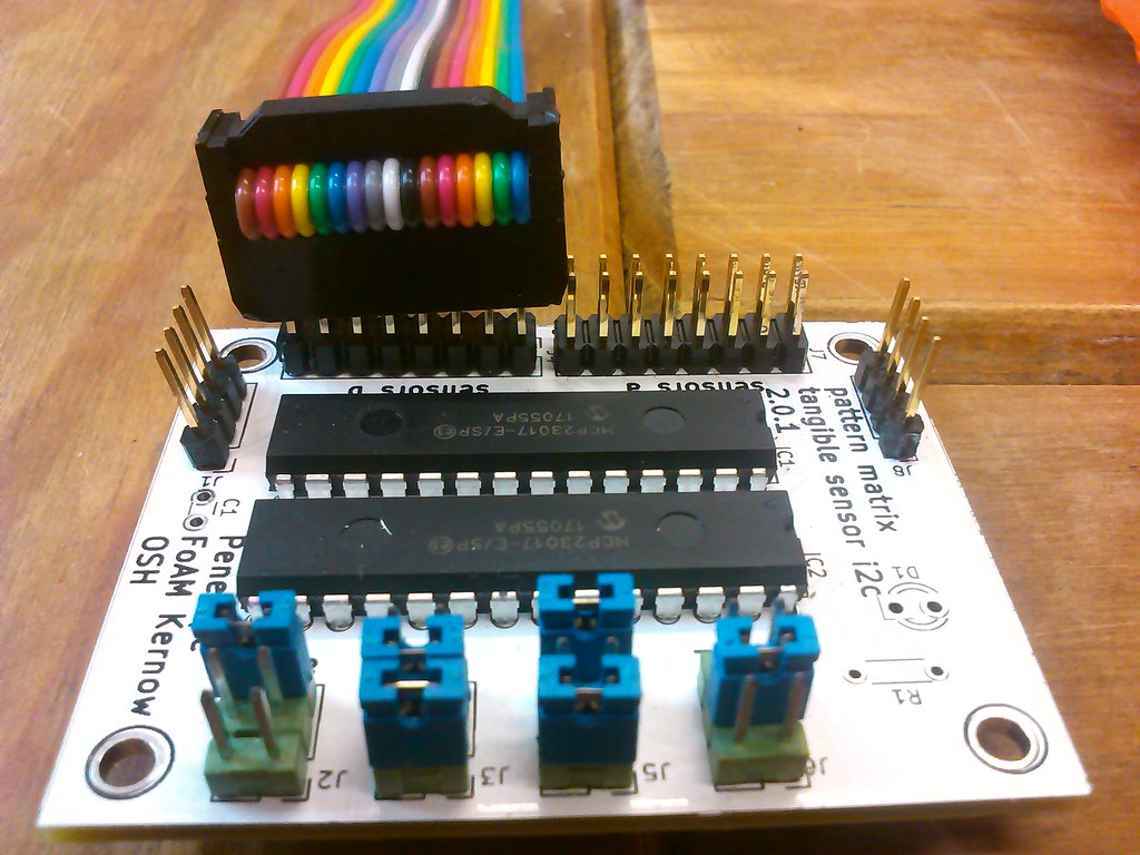
One of the problems with the prototype V1 pattern matrix was that the hand soldered connectors tended to fail between the sensors and the controller PCBs. With the V2 we also have many more connections to make so this needed to be solved in a more efficient manner. We decided to go with IDC connectors (insulation displacement connectors) which are solderless, you press the wires between tiny blades which automatically make the connection and hold the cable tight at the same time.
A few problems came up during this stage, firstly there is not enough room on the expander PCB's connections for the two 16 way IDC connectors to sit next to each other. This was solved by shaving a small amount of plastic from the edges of the two plugs - we can move them slightly further apart on the the next revision of this board. The other problem is that the 4 way IDC connectors that plug into each sensor location are slightly prone to tension breaking some connections temporarily. It's better than it was before, and easily fixed - but we will change them for more durable exhibition versions of the hardware.
Building the magnetic tokens

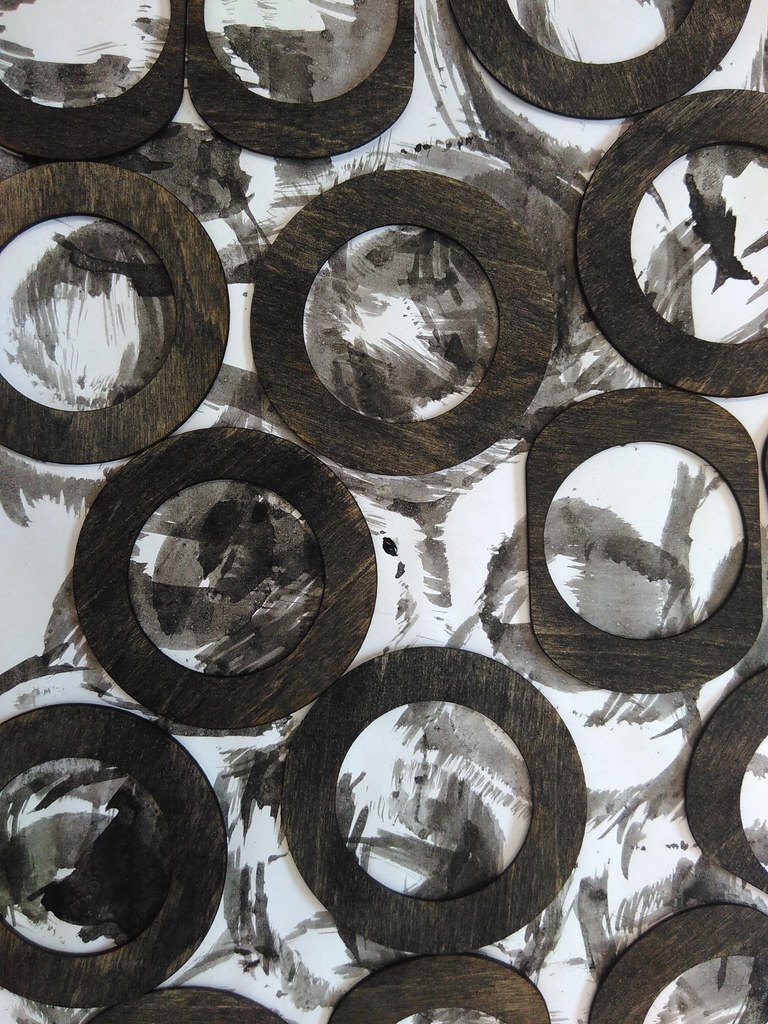
The tokens for controlling the Pattern Matrix were designed to house either one magnet or four, interchangeably, and were cut from beech using the CNC machine. Four different shapes were made to represent different organisations of the magnets/polarity inside. On either side of the beech token, we attached a laser-cut 1.5mm birch ply cover and doughnut-shape piece to allow the tokens to sit well on the sensor PCBs. The ply covers were again attached using silicon sealant.
With some of the tokens types, the rotational position can be detected, others the flip orientation, some of them both at the same time, so the tokens need to be coloured differently on each face, in order to tell which way up they are – we tried a few different stains – turmeric, tea, coffee, white-washing, finally settling on squid ink (1 in 10 mix with water). The grain of the ply is still visible, and it looks in keeping with the spalting on the beech wood. Sealing the ink proved problematic – in the end we compromised using Crystal Clear matt spray which works very well but is not ideal from an environmental perspective, so if you have better ideas do get in touch.
Once the token blocks had been CNC milled we could start gluing the magnets in place - being careful to keep the orientations consistent. One of the token combinations was tricky as the magnets needed to be glued in sequence to stop them working loose and snapping together. The all north or all south combination (the round tokens) could be produced with a single magnet to save resources - as we carefully designed the Hall effect sensors position to be close enough together to make them able to detect the field of a single magnet in this case.
New driver software
In order to effectively process the data from all 100 sensors, we need to be able to remove noise. Noise in this system comes from edge conditions when manipulating the tokens. For example if rotating a "N,S,S,S" token (reading north/south polarity in clockwise order) to the "S,N,S,S" position, we may encounter "N,N,S,S" or "S,S,S,S" as the magnets cross and overlap the detection range of the sensors. These readings represent different token blocks entirely, so would cause briefly incorrect readings. A similar thing happens if we pick up a token to flip it over - the sensors may temporarily be left in an incorrect state depending on how it was picked up.
In order to alleviate this we use probabilistic filtering to reject these brief edge cases. We can say that the probability of a rotation ("N,S,S,S" -> "S,N,S,S") or a flip ("N,S,S,S" -> "S,N,N,N") is more likely to occur than a new token appearing ("N,N,S,S" or "S,S,S,S") so we can delay the registering of the second case and wait to see if a rotation or flip of the current token is read within a fixed time span. The driver does this by storing a 'theory' and a 'current' value for each sensor location, and checking new observations against these - and only overwriting the current value with the theory after it is confident enough based on timing, that in fact a new token has been placed on the sensor.
In practice this seems to work well, as new tokens have a slight delay but the operation of switching them over takes longer to do, so it 'feels' right - while rotation or flipping is fast and read almost immediately so feels very responsive.
Thoughts and future plans

Having previously done a lot of 3D printing for making scientific research equipment, one clear benefit of working with wood is the ability to edit your piece after it’s finished – if you need a new hole in a specific place, it can just be added, rather than starting from scratch. 3D printing was hailed as a great prototyping technique, but wood seems far better suited in some ways. There’s also less waste, and fewer caustic materials in the production.
Building the wood pieces for the Pattern Matrix from scratch took four full days and a workshop full of equipment – the plan for V3 is to make an open source frame design that can be cut entirely on a CNC machine.
With regard to the electronics, we need to source and test new connectors for the sensors, perhaps for example using crimped connections rather than IDC. Another improvement to look into is whether we can solder everything on the lower side of the sensor boards (using surface mount) in order to remove the need for the protectors on the top.
The open source KiCAD software which we used for the electronics design, is a great tool for laying out circuit schematics and turning them into PCB designs. However minor issues like the Hall effect sensor solder pad size and connector spacing show that scales are as important to in the final design as getting the circuit correct. We will keep this same modular system for the future, but we can tweak the PCBs to fix these issues for future iterations of the pattern matrix.
We investigated some further ideas during the course of this build which may be worth pursuing in the future, such as haptic feedback – using tiny piezo speakers or small motors, both of which needed more hardware to increase the voltage to drive them with sufficient power. Additionally we have added a seven segment LED display for visual feedback for debugging when no screen is present, which might be handy to have as standard. We also did some preliminary investigation into Augmented Reality as a way to place 3D objects over the pattern matrix grid as a potential method for further explanation and feedback for tangible programming.
All plans, schematics and source code can be found here.

Created: 15 Jul 2021 / Updated: 15 Jul 2021
